Between January 1997 and February 2000 the instrument-control-software for the Focal Reducer and Spectrograph (FoRS) instrument was developed, implemented and tested - in the lab as well as during real operations at the Very Large Telescope at Cerro Paranal, Chile. Since April 1999 the software is used in normal operation mode. The following text gives a short description of the FoRS project and the developed instrument-control-software.
At Cerro Paranal, a peak with an altidude of 2635m, situated within the chilenian Atacama desert the Very Large Telescope (VLT) of the European Southern Observatory (ESO) is under construction. In its final configuration consisting of four 8.2m telescopes (together with a few smaller auxiliary telescopes) it will be the biggest and technologically most advanced observatory in the world. The four telescopes can be operated on their own or used in a combined focus mode (with an effective diameter of the primary mirror of 16m).

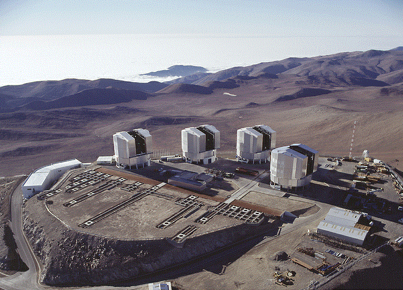
View from the southeast to Paranal, in the background the pacific ocean covered with clouds. From left to right the four telescopes ANTU, KUEYEN, MELIPAL und YEPUN (The names are the mapuches' words for "sun", "moon", "cross of the south" and "sirius"). At the left side the control building is visible. In the foreground foundations and trails for the three moveable auxiliary telescopes are to be seen. In the center within the shadow of ANTU the laboratory for the combined focus is situated (picture taken December 8th, 1999, copyright ESO).
Only focal instruments (like cameras, spectrographs) attached to the foci of the telescopes will allow to determine the physical properties of the astronomical objects under investigation. Because these instruments must be bigger in size and most efficient compared to actual constructions frontiers of nowadays optics, mechanics, electronics and control loop technics were reached.
The first instruments for the ESO VLT were built by scientists from the Landessternwarte Heidelberg and the observatories of the Georg-August-Universität Göttingen and the Ludwig-Maximilians-Universität München. The instruments are two (almost identical) multi purpose instruments which are called FoRS1 and FoRS2 (focal reducer and spectrograph). They allow to investigate the faintest and most remote Objects in the universe and will play an important role in answering the prominent questions in astronomy (e.g. dark matter, early universe, expansion, black holes, forming of planetary systems). FoRS1 and FoRS2 are the result of one of the most advanced technological studies ever made for an earthbound astronomical instrument.
The highly motivated team, consisting of technicians, optic and electronic engineers, software developers and astrophysicists gained the race against other groups who also applied when ESO anounced this project throughout Europe. Pictures and spectra obtained with FoRS went round the globe and have been appreciated by the scientific society.

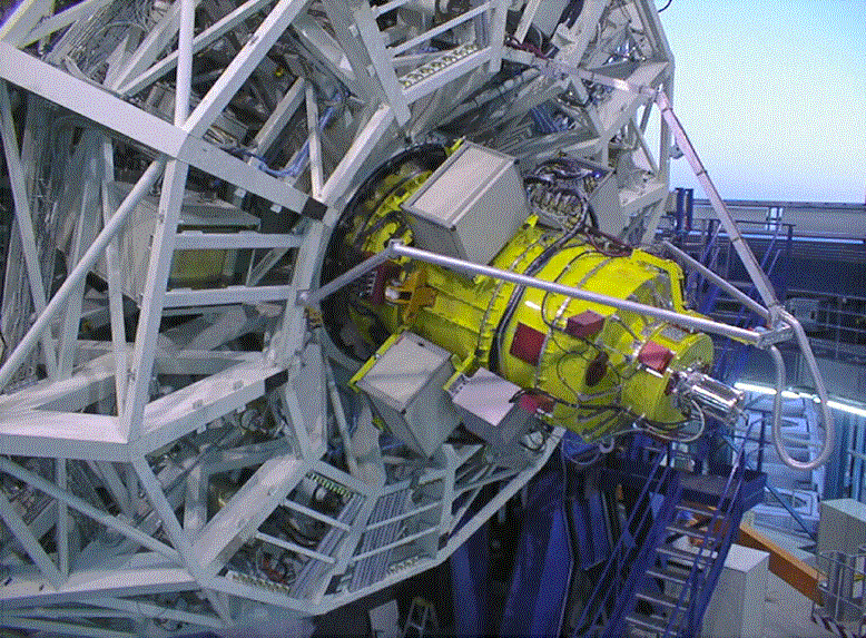
FoRS1 at VLT telescope ANTU (picture taken at november, 26th, 1998, copyright ESO).

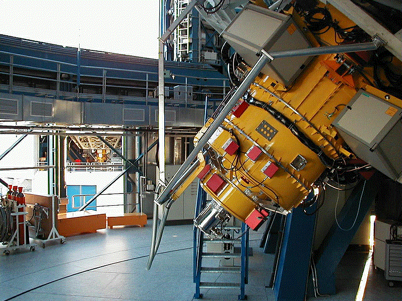
FoRS2 at VLT telescope KUEYEN, in the background FoRS1 at telescope ANTU is visible through the open doors of the ventilation (picture taken at november 17th, 1999, copyright ESO).
The costs of the whole FoRS project amounted to over 20 million DM and were divided by the german minister of science and ESO by 4:1. Besides that the three institutes provided man power as well as laboratory and mechanical workshop capacities.
Further informations about the FoRS project can be found on the FoRS homepage of the observatory of the Ludwig-Maximilians-Universität München (publications, documents, pictures, videos) and ESO (press releases, technical details, pictures, videos, FoRS user manual).
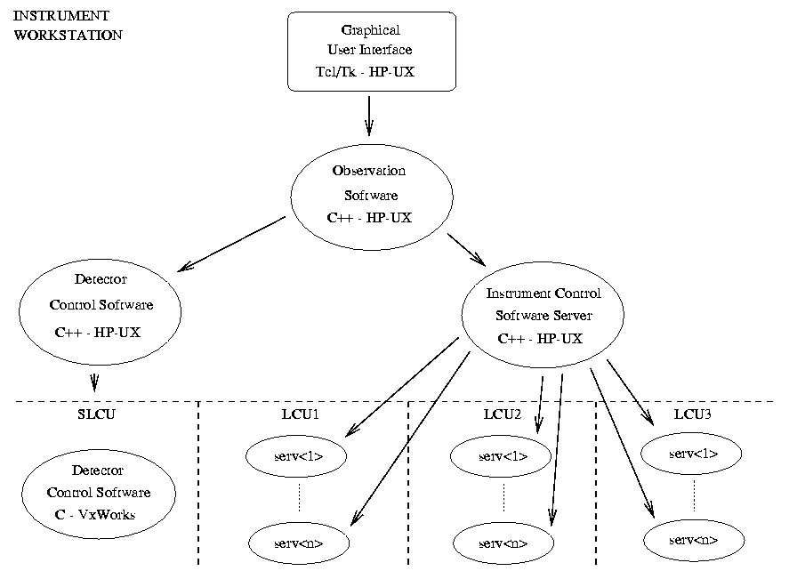
The FoRS software runs on a distributed computer network consisting of a HP UNIX-workstation, three local microprocessor workstations (68k, powerPC) and a local microprocessor sparc station. The microprocessor workstations (also called local control unit, LCU) are equipped with the real-time operating system VxWorks. The software is built in a multi-layer architecture and is founded upon the VLT software which provides general services like a message system, a real-time database and an error and logging system. The following figure shows the structure of the FoRS software:

Structure of the FoRS software: The observation software which is addressed via the graphical user interface, translates the requirements for an observation into a sequence of single commands for the detector and instrument control software. These commands are then forwarded to individual command servers. Not shown are the observation support software which is used for preparation of observations as well as the maintenance software, which is used to replace components (filters, grisms, masks) and to calibrate the instrument.
The instrument-control-software (ICS) consists of a workstation part and three different parts which run on the individual LCUs (local control unit). The ICS server process on the workstation is responsible for coordination of the different tasks, distribution of commands and supervision of the instrument. Control of individual drives (e.g. filterwheels, MOS-arms, camera optics etc.) and recording of characteristic values (e.g. temperatures, switch positions, drive positions) is performed by individual command servers on the different LCUs.
One reason for the outstanding data quality of FoRS is related to the excellent positioning accuracy of its various drives which allow to move slitlets, masks, filters, grisms etc. Every drive within the instrument is controlled via a PID control loop. This allows very accurate positioning. Most of the drives can be moved in parallel.
For calibration purposes a number of spectral and flatfield lamps are installed inside the instruments. For each of these lamps a individual command server allows to return the actual status of the lamp (e.g. to check for over temperature status, on/off status, failure) as well as to switch it on or off.
Control of temperatures is a very important task in order to avoid additional heat dissipation at the telescope and to control temperature dependent drives (e.g. camera focus). Therefore changes in temperature are supervised by temperature sensors installed at various places inside the instrument. When the allowed range in temperature change is exceeded an alarm is generated on the instrument workstation.
The voltages of all powersupplies mounted at the instrument are supervised by the instrument-control-software. A failure causes an alarm to be generated on the instrument workstation.
In order to avoid any additional heat dissipation at the telescope the whole electronic racks (including the LCUs) are cooled by a closed water curcuit to the actual ambient temperature. The cooling flow as well as the water temperatures inside all electronic racks are supervised. In case that the allowed range is exceeded an alarm is generated on the instrument workstation.
Each function of the instrument can be simulated on LCU level as well as on workstation level. This is important not only for software tests, because tests can be performed without any hardware being attached, but also for testing observing sequences (e.g. during daytime). This avoids that precious observing time gets lost due to erroreous observing scripts.
Every change in the position of a drive or switch etc. is logged in a global logging system. In addition at the end of each exposure the actual status of the instrument is written to a data file, which then is archived together with the data by the observation software. This allows to reconstruct the status of the instrument for what time ever.
January 1997 till February 2000
Mantel,K.H., Meisl,W., 2000:
``FORS Instrument Control Software - LCU Part - User Manual (2.0)''
[zipped PS-file 686334 bytes],
FORS Software Documentation, Part 3, VLT-MAN-13110-0106.
Mantel,K.H., Meisl,W., 2000:
``FORS Instrument Control Software - LCU Part- Maintenance Manual (2.0)''
[zipped PS-file 851392 bytes], FORS Software
Documentation, Part 6, VLT-MAN-13110-0109.
Mantel,K.H., 2000:
``FORS Instrument Control Software - Workstation Part - User Manual (2.0)''
[zipped PS-file 227513 bytes],
FORS Software Documentation, Part 2, VLT-MAN-13110-0105.
Mantel,K.H., 2000:
``FORS Instrument Control Software - Workstation Part - Maintenance Manual (2.0)''
[zipped PS-file 157122 bytes], FORS Software
Documentation, Part 5, VLT-MAN-13110-0108.
Muschielok,B., Gaessler,W., Mantel,K.H., Meisl,W., Seifert,W., 2000:
``FORS Operating and Maintenance Manual (2.0)''
[zipped PS-file 496838 bytes],
FORS Software Documentation, Part 7, VLT-MAN-13110-0103.
This project is supported by the German Federal Ministry of Science and Technology with ID-Nos. 052HD50A, 052GO20A and 052MU104.
| Home | | | Instrumental Development | | | Astronomical Observations and Data Reduction | | | Power Engineering | | | Publications | | | FORS Calendar | | | Guest Book | | |